Production time cut from three weeks to six hours using additive manufacturing
Published: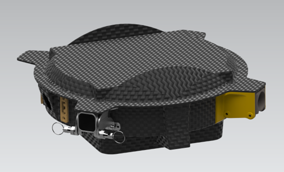
Challenge
To demonstrate how design for additive manufacturing (AM) and metallic AM can optimise fittings for rotor arm fixtures for lightweighting, mechanical stiffness and enhanced functionality.
Background
Tilt Angle Drones is a Blackburn-based company specialising in the design and production of bespoke uncrewed aerial vehicle (UAV) systems and payloads. Their uncrewed vehicles are designed around custom-built carbon fibre composite airframes, which can be tailor-made to the customers’ requirements.
They have previously utilised additive manufacturing using fused filament fabrication (FFF) - which is the layer-wise deposition of heated polymer filament extruded through a nozzle - as well as conventional methods, like machining, to produce fixtures and fittings for their UAVs, resulting in large material wastage and an increased lead time. Additionally, through conversations with their customers, they have found that their current method of fixing the rotor arm to the drone, using a bolt to position the arm during flight, is not user-friendly, requiring the customer to remove the bolt to fold the rotor arms down.
They were interested in investigating how design for additive manufacturing (DfAM) and metallic AM methods can be used to optimise their bracket fixture, and approached the AMRC North West, funded through Blackburn with Darwen Borough Council’s share of the UK Shared Prosperity Fund (UKSPF).
Innovation
To fully leverage the advantages of metallic additive manufacturing, the bracket design was re-engineered using DfAM principles. The original concept was subjected to topology optimisation within Ansys Workbench, targeting a 40 per cent weight reduction, while preserving mechanical stiffness under defined loading conditions.
Based on requirements from Tilt Angle Drones, each rotor arm is expected to endure a maximum static load of 20 kilograms. To ensure structural safety, the design incorporated a safety factor of two, resulting in a design load of approximately 400 N per rotor arm. This allowed the optimised bracket to remain lightweight, without compromising its ability to withstand operational stresses during flight.
Upon completion of the optimisation process, Ansys generated a mesh model that captured the ideal material distribution. However, due to the mesh’s organic geometry and surface complexity, it was not directly manufacturable via additive manufacturing methods. To address this, the optimised form was reconstructed in Siemens NX, where it was converted into a manufacturable solid CAD model.
As part of the lightweighting strategy, a body-centered cubic (BCC) lattice structure with a strut size of 0.5 mm was integrated into the interior of each rotor arm within the CAD environment. This internal lattice further reduced the overall mass, while enhancing the structural performance typically demanded in aerospace and UAV applications.
Beyond structural optimisation, the bracket assembly was redesigned for enhanced functional efficiency; a new quick-release mechanism was developed, featuring a spring-loaded index plunger. When actuated, the plunger allows the rotor arm and bracket body to pivot downward, folding the arms flush with the drone’s frame, significantly improving portability and ease of deployment.
To support user flexibility and potential future configurations, the bracket was designed in both circular and square cross-sectional variants, enabling customers to select the geometry best suited to their rotor arm preferences, or performance requirements for final production.
Result
To validate the structural integrity of the newly optimised design, ANSYS Workbench's Static Structural finite element analysis (FEA) was employed. The simulation assessed how the design performed under varying static loading conditions, particularly focusing on different rotor arm lengths - a critical factor influencing structural stress and deflection.
Three arm lengths were evaluated: 400 mm, 500 mm and 600 mm, each incrementally increasing the moment applied to the rotor bracket. Both circular and square cross-sectional geometries were analysed.
Results showed exceptional stiffness across all variants: maximum deformation remained below 0.25 mm, while average deformation stayed under 20 µm, a strong indication of mechanical stiffness.
Further scrutiny was applied to the bracket hinge, especially at the maximum rotor arm length of 600 mm. Here, the design demonstrated a maximum deformation of just 1 mm, with an average of 0.30 mm - well within acceptable limits for high-precision applications.
A prototype of the optimised design was produced using laser powder bed fusion (LPBF) technology on a Renishaw AM500Q platform, utilising AlSi10Mg - a corrosion-resistant aluminium alloy known for its high strength-to-weight ratio and mechanical durability.
This shift from conventional manufacturing to additive manufacturing delivered dramatic benefits. Whereas traditional production required up to six weeks to deliver eight bracket fixtures, the LPBF process achieved four fully printed brackets in under six hours, excluding minor post-processing.
The use of LPBF also minimized material waste due to its inherent nature of adding material where necessary; this is a critical gain in both sustainability and scalability.
Initial mechanical testing further validated the optimised fixture’s performance. Compared to the legacy design, which deformed 300 µm in average under a 7 kg load, the new bracket is engineered to handle a static load of over 20 kg with the same maximum deflection of 1 mm, even at the extended 600 mm arm length.
Impact
The expertise from the AMRC North West team was invaluable to Tilt Angle Drones.
The company had struggled to find a suitable replacement for an old design of a tubular CFRP arm mount, as their original was extremely strong but required a manual fixing to be utilised, which was not seen as acceptable in the modern UAV world.
Although they had a couple of solutions in design and trial, non-seemed fit for manufacture, or met their own high expectations.
What the AMRC North West team designed was a slim-line, quick release arm union that is cheap to manufacture and will withstand four times the amount of stress with minimal deflection of the original design.
This means they now have a suitable, stress tested and easy to manufacture arm union, and can move forward with manufacturing their first medium lift capacity multirotor platform for UK sales.